
Vibe-Coding a PCB: What We Learned Letting Claude Design a Mixed-Signal Schematic

November 9, 2026
Why we explored AI-assisted hardware design
Not long ago, we explored Vibe Coding in embedded software, examining how supervised AI agents handle genuine engineering tasks. Starting with firmware made sense. Tackling hardware posed a much greater challenge: unlike software, errors in schematics, symbol libraries, or part selection carry physical consequences that unit tests simply cannot catch.
Over the past year, Focus has been bringing AI into every stage of hardware development as part of a company-wide AI program. One result is our KiCad AI Workbench, built by our hardware AI team. KiCad stores designs as plain text, so an agent like Claude can read and edit a schematic directly instead of working around a closed CAD tool.
To see how far that goes, we ran a full mock project. We handed Claude the design work block by block, with one rule: nobody places a component by hand. Six working days later we had a 12-sheet mixed signal schematic with 302 components. This post covers how we set it up, where the AI excelled, where it struggled, and how the effort compared with designing the same board by hand.
The baseline: a research device we already knew
To evaluate the development efficiency of an AI-driven approach against traditional manual methods while strictly adhering to our design quality standards, we ran a direct comparative experiment.
We selected a precision mixed-signal research device for neural signal acquisition that our team designed a year ago as our benchmark. Because its architecture, circuit requirements, and baseline engineering hours were thoroughly documented, we could critically evaluate each block generated by Claude against a deeply familiar reference design. Consequently, this study focuses specifically on schematic design and circuit development rather than high-level system architecture.
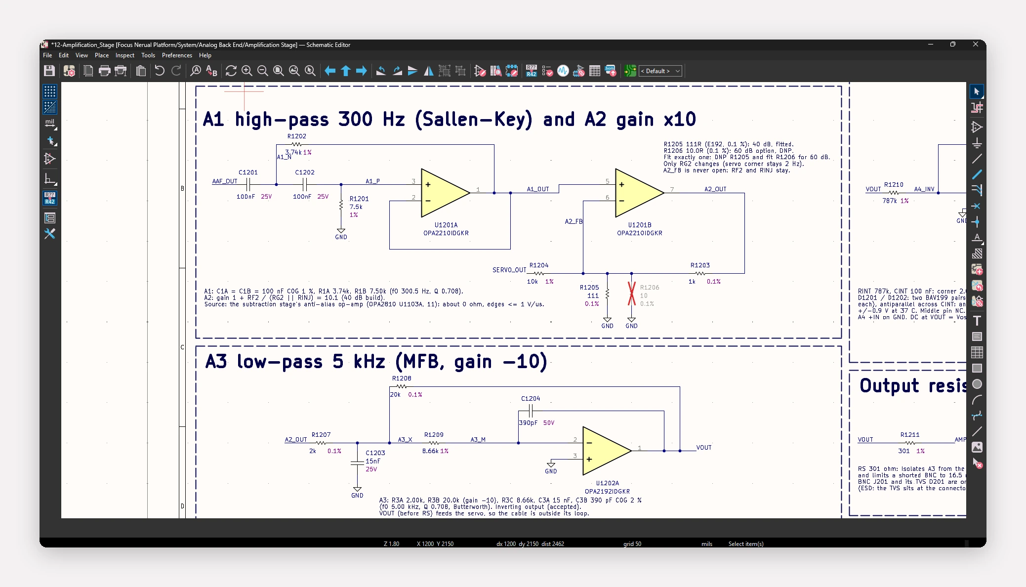
The board is dominated by precision analog circuitry. An instrumentation amplifier front end feeds a back end that uses a DAC-generated signal to cancel an unwanted artifact, followed by an amplification stage. Around that sit an STM32 microcontroller, a USB-UART interface, an external ADC and DAC, and separate digital and analog power trees.
The rules were strict: no manual component placement in KiCad, and as little direct schematic work as possible. Claude handled component selection, library creation (symbols, footprints, and 3D models), SPICE simulation of the analog blocks, and the schematics themselves. Our engineer's direct edits ended up at roughly 2.5% of all schematic changes, almost all of them cosmetic. We believe even those can be avoided by defining style guidelines or adding skills.
How we set it up
Ticket-style prompts. Each functional block got a prompt written like a development ticket: objectives, quantitative requirements, work stages, and exit criteria. Here is part of the prompt for the subtraction stage:
“The CMRR of the differential amplifier will be key for subtracting the artefact. It should be at least 100dB, accounting for component tolerances, in the 100 Hz to 50kHz range. [...] The differential amplifier should also implement a low pass filter at 100kHz. [...] The amplifier in differential configuration architecture could be changed. Explore other options.”
Staged context resets. Every block went through three stages: design, simulation, and implementation. We cleared the context completely between stages. Before each reset, Claude wrote the handoff prompt for the next stage, including the model and effort level it recommended.
Parallel worktrees. Each ticket lived on its own git branch and worktree. That let us run up to three blocks at once, each in a different stage. On the busiest day, six tickets moved forward.
Independent review. To validate the design, an independent subagent (completely isolated from the sheet creation process) conducted a full schematic review. It drew upon KiCad's ERC, our custom internal rules checker, a dedicated electrical analysis tool, and a BOM inspector to identify out-of-stock or obsolete components. We also took full advantage of KiCad’s vibrant open-source ecosystem to enhance Claude's capabilities.
Results by area
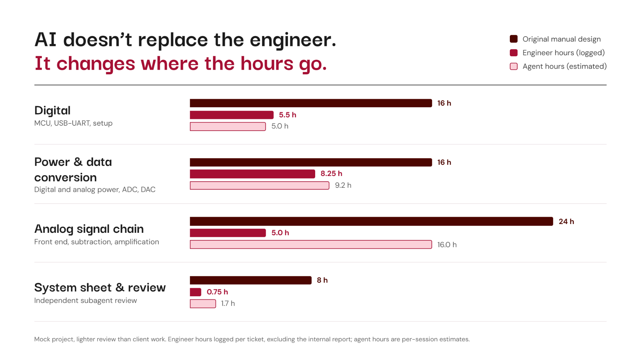
Claude completed every task it was given. Quality held up across all areas, but speed depended heavily on the kind of circuit.
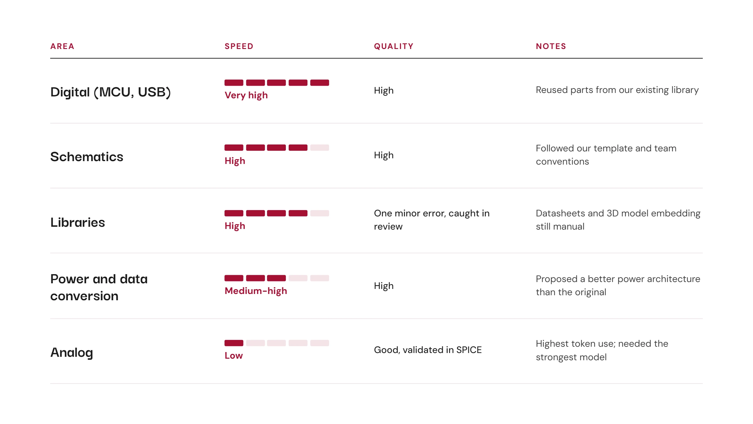
Digital is where Claude shines. The MCU and USB sheets went fastest. Claude found reusable parts in our library and selected only the new ones it needed.
Libraries were nearly clean. The one error was a GPIO count of 114 instead of 115 on the STM32 symbol, caught by the independent reviewer. The two most annoying problems were that most manufacturers block automated datasheet downloads, and that generated 3D models still need to be embedded in footprints by hand. The first can be solved with a datasheet repository or a company-wide component library.
Power and data conversion required design decisions. Claude had to choose an architecture that met the performance requirements, then select parts and build the sheets. It proposed several options and, within the scope of our review, settled on a power architecture that improved on the original. It did the same when selecting the ADC and DAC.
Analog was the slowest and most expensive. Precision analog needs more care in topology and part selection, and we asked for SPICE validation, which the workbench doesn't support natively yet. The designs were coherent and worked in simulation, but every analog design stage ran on Claude Opus 5.5 High, the most capable and most expensive model we used.
Four lessons from the run
Method matters more than model
On the MCU sheet, simple tasks such as adding a user button took longer than expected, so we asked Claude to audit its own time. About three of the roughly five and a half hours on that sheet went into pinout and drawing. The biggest waste was working out pin, field, and label positions from rendered images instead of reading coordinates with a script.
Claude then built its own tools to read and edit schematics directly, and token use for schematic edits dropped considerably in later sessions. Model choice still mattered: Opus handled the design-heavy tickets, while Claude Sonnet 5.5 did well on implementation and more mechanical work.
Size your simulations before you run them
One unbounded DAC sweep produced 2.6 GB of results and ran the machine out of memory. From then on, every simulation was sized up front: steps, saved nodes, file size per run, and parallel jobs. The next DAC run covered 95 corner cases in about three minutes and 1.1 MB.
The agent builds exactly what you ask for
The BOM check found an obsolete 100 nF capacitor used 44 times, eight parts out of stock at DigiKey, and thin-film resistors with 55,000-unit minimum orders. Our prompts never asked for in-stock parts, and the agent did what the prompts said. Supply chain constraints have to be in the spec, or better, checked continuously by tooling and in the project context.
Review becomes the bottleneck
With three worktrees running, the bottleneck moved from generating designs to reviewing them. The independent review found zero errors, but four of its ten warnings were real design issues. For example, the MCU's voltage reference could exceed its analog supply by about 50 mV in the worst case. Breaking the work into smaller, stacked pull requests makes the review load easier to manage.
The bigger picture: AI across our hardware workflow
The KiCad workbench is one part of a broader effort to bring AI into how Focus builds hardware products. All of these tools share the process, libraries, and review standards our teams already use.
- KiCad AI Workbench. Agentic schematic development on text-based design files, with component search, parameter autofill, and symbol and footprint generation built on our existing component library.
- AI skills for Altium. Many clients require Altium, so we are building a toolset there as well: component search with live distributor data, library audits, BOM risk analysis, pull request review, documentation agents, and a release validator that checks manufacturing outputs before they go out. Here, we leverage Altium’s script to interface with and modify Altium files directly.
- Tool evaluation. Before committing to KiCad, we ported one of our most demanding designs, a rigid-flex HDI board, to it. For the roughly 80% of our boards that are fully rigid without microvias, KiCad meets our quality bar.
- Firmware. Supervised agents for embedded development and verification, which we covered in our Vibe Coding article.
How long each part took, and what we concluded
The full schematic took six active days between October 27 and November 4: 11 tickets, 26 agent sessions, and 79 commits. The windows between each day's first and last commit add up to about 38 hours, while logged engineer time was about 23 hours, including writing the internal report. Part of that gap comes from parallelism: agents kept working while the engineer reviewed other blocks.
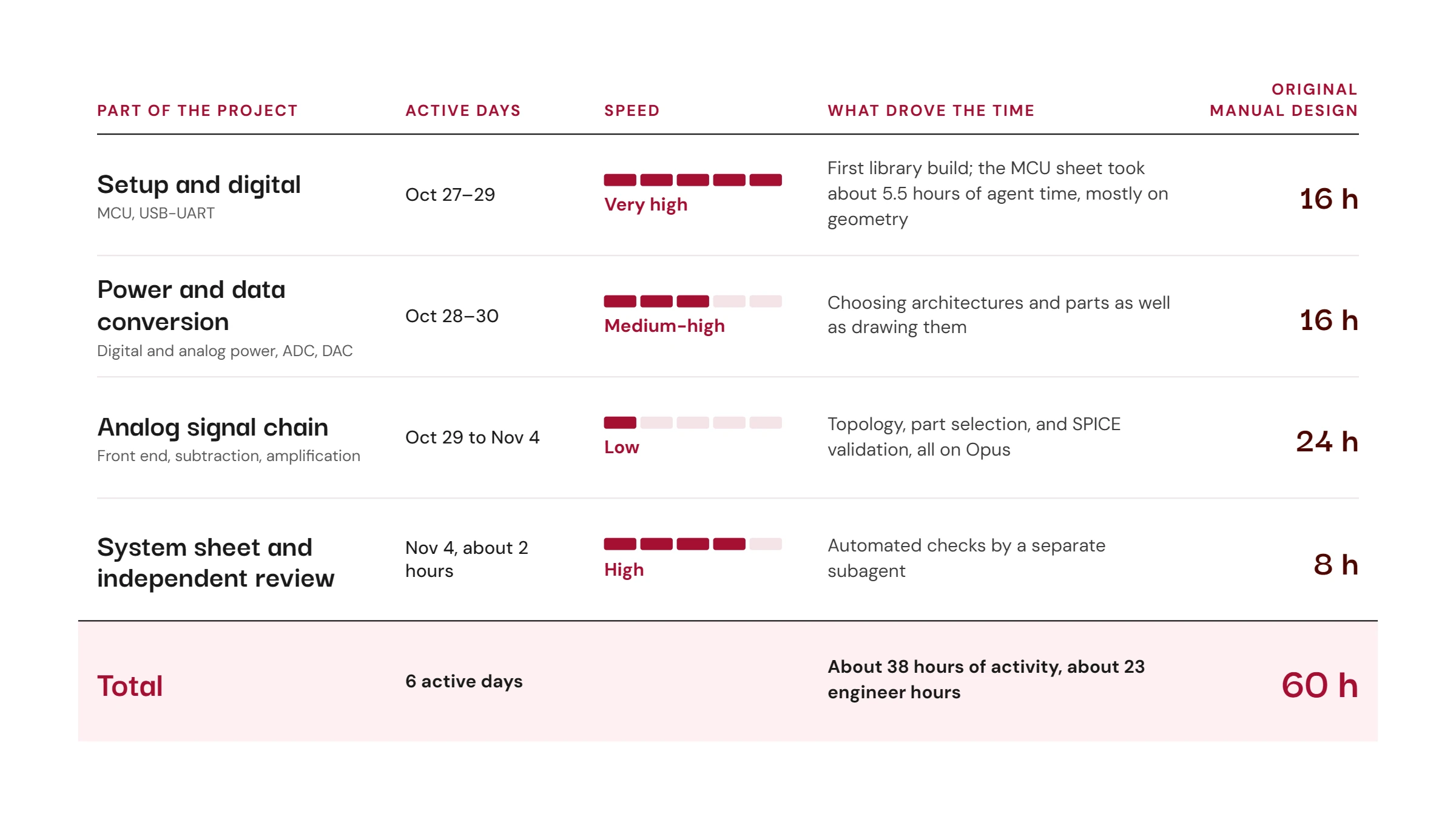
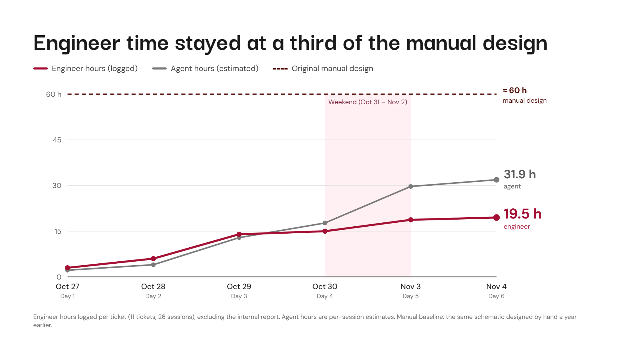
The spans overlap because blocks run in parallel, and they include time spent waiting for review. Only the MCU sheet had its agent time measured in detail, so the next run will log model, effort, time, and tokens for every session.
In summary, the baseline schematic design required around 60 hours, whereas this trial demonstrated that engineering time could be cut to roughly one-third. While impressive, this figure requires context: to streamline testing, we minimized engineering reviews. In practice, we anticipate a 30% to 40% reduction in development time for actual projects, shifting primary engineering effort toward thorough code and design reviews.
What we take away from the run:
- The tools are ready for real projects, with more review. This was a mock with a lighter review than a client project gets. On real work, part of the time saved on drawing should go into reviewing and making sure Claude’s design meet specifications
- Speed depends on the circuit. Digital and power blocks move at a pace that changes how we plan schematic work. Precision analog still needs the strongest models and an expert checking every decision.
- The engineer's job shifts from drawing to specifying and reviewing. Writing a good ticket and reviewing well are now the core skills, as we found in firmware.
- Open design files are a strategic advantage. Agents can only work this way on design files they can read and edit, and KiCad's text format allows that.
- The tooling improves with every run. Each session logged lessons for future skills, 156 in total. They now feed a dedicated schematic skill, along with native SPICE support, continuous BOM stock monitoring, and the next step: layout.
- Overall token consumption was high: Even though digital design was faster, the overall token consumption was high. Designing, understanding, creating, modifying, and reviewing a schematic requires a lot of work from the Agents, which we are pushing to complete the tasks.
So, what does this mean for our business?
This run confirmed what we first saw in firmware. AI doesn’t replace the engineer, but it saves a lot of engineering time by changing where the engineer’s hours go. Instead of spending innumerable hours drawing the straight lines that make up a schematic, we spend most of our time working on specifications together with our customers. That maximizes the value of our expertise, and it’s where we want our team spending its time.
On top of that, fewer engineering hours mean a strong reduction in overall cost. At Focus, we see this as a huge opportunity: it makes applications that weren’t financially feasible interesting again, bringing a lot of old ideas back to life. We think a clear line will form between companies that embrace these new tools to maximize the output of their teams and those that don’t. We see Focus as an enabler for its partners in that shift, bringing these innovations to their teams and helping them adapt to the latest tools.
These new methods also let development teams reach deliverables and verifiable results sooner, which means quicker iterations. On real projects, we expect schematic development to take 30% to 40% less time. For a team racing toward a first prototype, a pilot build, or a funding milestone, getting to a first board earlier matters.
They also let developers explore more options in parallel. When a candidate architecture takes hours instead of days, we can compare several before committing. That’s how this run ended up with a better power architecture than our own original design.
On client work, part of the time saved goes straight back into review. Every block is still checked by an engineer, backed by automated checks for electrical rules, our internal design rules, and BOM risk.
We’re also clear about the limits. Precision analog, the circuitry at the heart of most medical and sensing devices, still needs the strongest models and an expert checking every decision. That’s where experience keeps making the difference, and where our engineers stay closest to the work.
If you’re figuring out where AI fits in your own hardware development, let’s talk. We’re happy to share what we’ve learned.
Stay focused on what’s next
Stories, ideas, and insights from the world of technology, product development, and innovation.




Contact
Let’s Talk!© Copyright 2026 Focus. All Rights Reserved.