
USB-C Power Delivery: A simple guide to ruining three boards before making it work

July 27, 2026
As a hardware/electronics designer, nothing excites me more than blowing up a board and figuring out what happened. In the end, we’re not that different from firefighters: the real thrill starts when the flames show up. Your client or boss probably won’t think burning PCBs is all that exciting, though. For tips on how to handle that part, DM me.
Today, I want to tell you how I managed to kill three boards before I got every USB-C and USB-PD feature working, so you can either enjoy the same step-by-step chaos I did or get bored by the success of making it work on the first try. Your call.
What is USB-C?
With more than ten years since its first spec and nowadays being a mandatory interface for pretty much any device, USB-C barely needs an introduction. Yes: it’s the reversible one that finally ended the “is it upside-down?” ritual.
For most people, that’s the only feature that matters. But beyond that, USB-C adds two big things for designers: higher power capability and roles defined by application (policy) rather than by the physical connector.
With micro or mini-USB, there wasn’t much flexibility: a Type-A port was the power source and the communications host, and Type-B was the peripheral and power sink. You might be thinking, “that’s why OTG exists.” While that’s true, OTG kept power and data roles coupled and was hardware-dependent as you needed a special OTG cable to flip roles.
So, in USB-C, if the connector itself is role-neutral, how do devices determine who takes the host role versus the device role and who is the sink versus the source? That’s where the CC pins come in.
The mechanism is simple: each side presents a known pull resistor where the advertised pull-up (Rp) identifies a Source/host preference, and the pull-down (Rd) identifies a Sink/device. The voltage seen on the CC pin tells each side what’s on the other end and sets the initial roles with no special cables and no guesswork.
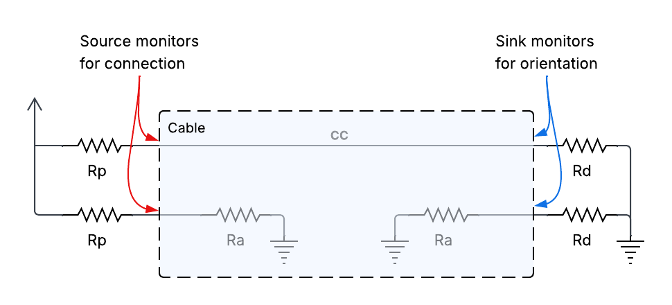
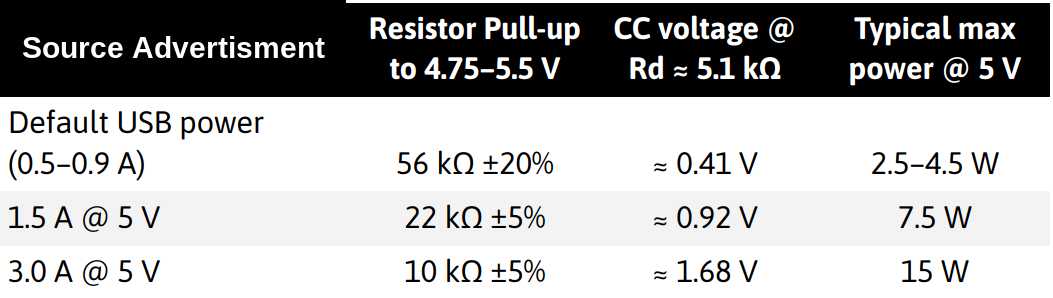
On Type-C, the Rp pull-up has standardized levels that advertise how much current a Source is willing to provide at 5V. The Sink presents a fixed pull-down, Rd = 5.1 kΩ (nominal), measures the CC voltage, and from that infers the advertised current tier, no PD required.
Another neat trick is that only one of the two CC pins (CC1/1CC2) connects through the cable while the other one stays high impedance (ignoring active cables here). Enabling the host to know which way the plug is inserted.
Why do we care? Because at USB 3.x speeds, the connector is symmetrical, but for SuperSpeed pairs that’s not true anymore. If you don’t flip the pairs with a USB-C SuperSpeed “flip” mux, you leave a stub on the unused differential pair and wreck your eye diagram (Sadly, I haven’t blown a board because of that yet… maybe the next one?).
Quick recap (the honest one)
Even with plain USB-C (no PD), you already get:
- A reversible plug, so you can plug your phone in at 2 AM with the lights off without doing the “braille-by-fingertips” routine.
- Role-neutral ports defined CC, not by connector gender.
- Up to 15 W via Type-C Current (5 V × 3 A) — roughly 2× old USB BC 1.2 (7.5 W).
If you need to go beyond fixed 5 V negotiate voltage and current, switch power direction without unplugging, and exceed 15 W into laptop-class power that’s exactly what USB Power Delivery enables.
What is USB-PD?
The name kind of says it all, right? Power Delivery over USB. Older USB connectors had tiny power budgets for today’s use cases, so slapping “PD” next to USB-C sounds like “more watts.” Yes, but no.
USB Power Delivery is a communication protocol (carried over the USB-C CC pin) that lets two devices negotiate voltage, current, and even the direction of power. It’s not the shape of the connector, it’s the conversation that happens after you plug in. No PD on one side? You fall back to plain Type-C Current (5 V @ 1.5/3 A).
One of PD’s biggest wins: insanely high power. We at Focus are now working on a system (I can’t tell you much about it yet!) That uses USB-PD to draw power up to 240 W!.
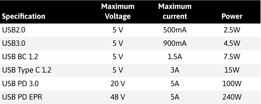
But USB-PD offers much more than raw power: it enables dynamic role changes. This means changing the roles once they are already established. Even the power and data roles are independently decoupling power and data. That means you can have a device driving the USB negotiation while being charged by the other side without using weird cables or hacks.
First board ruined: No PD when your app’s roles seem off
As we’ve been saying, a USB-C connector gives you two kinds of functionality: data and power. Regardless of the data rate, the protocol, or the wattage, when you design a system with USB-C you’re really solving two problems: how the data path will work, and how the power path will work.
First thing: decide what role your device will take on that shared bus. On the data side, will it host and control the link? or will it be a peripheral attached to a host? On the power side, will it provide power or be powered by the far end? USB-C is flexible enough that you can even answer: it depends.
Let’s look at the roles the latest USB-C spec defines:
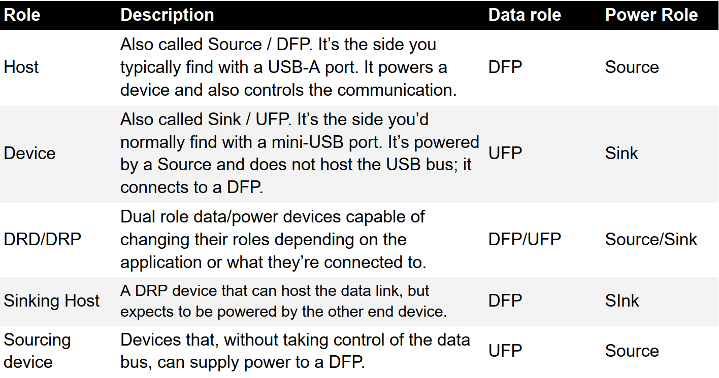
Ok, so it seems clear: from what we said in the previous section, power roles are determined by the kind of pulls on the CC lines, while it’s reasonable to assume the data role is decided on the data bus itself. After all, with USB-A/USB-B there were no sideband signals to control that, so why would there be now? If you want DRP behavior, you might think you just need to toggle the pulls dynamically and you’re done. Congratulations! You’ve just discovered why your board doesn’t work.
The neutrality of the connector and the new USB-C pinout simplify things a lot, but at the same time, it exposes devices to situations that just weren’t possible with USB-A or mini-USB. For example, what happens if I connect two USB-C lamps to each other? Or two chargers to each other? The answer is: nothing.
I assume you didn’t think the creators of USB-C wouldn’t account for some maniac (you, on a wild Saturday night) trying to plug two USB-C chargers together to see if something explodes
There are non-functional connections in USB-C (e.g., host-to-host or device-to-device). To prevent bad behavior, the connection-establishment process in USB-C is driven by state machines.
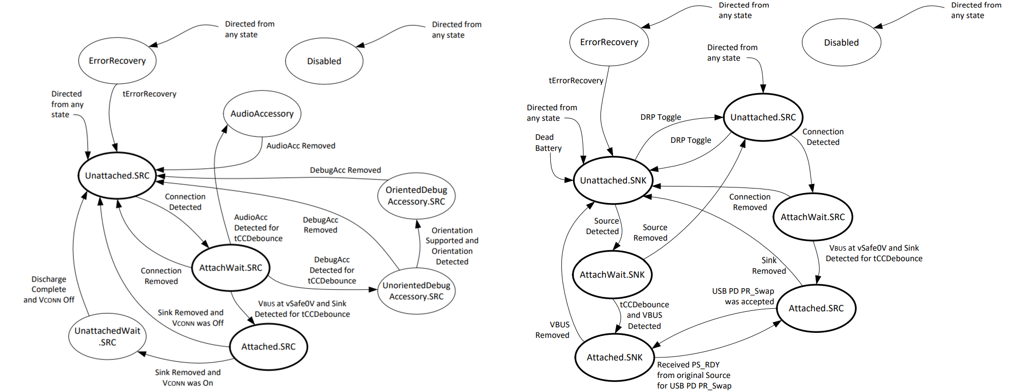
These state machines in the USB-C spec are pretty straightforward: first, you watch the CC lines to figure out who’s on the other side; based on that, you enable (or don’t) VBUS into your system.
For DRP devices, what happens on CC? Simple: they toggle their pulls over time. That’s necessary because, say, if a DRP plugs into a Source-only device, that Source won’t enable power until it sees an Rd on CC. The toggle is what makes the attachment happen.
But there’s a wrinkle: what if you connect two DRPs? Is the initial state 100% timing-dependent? As our friend Robert Feranec would say: it depends!.
USB-C defines try.SRC and try.SNK states, which can be modeled as preferred roles. After CC is detected and before moving to Attached, each side can ask the other to flip if the emerging role isn’t its preference. If both sides prefer the same role, then yes: the initial outcome depends on the advertisement toggle timing.
So, the initial roles you can land on at connection time are essentially host and source. DRP/DRD devices can be any of those, but after entering the attached state, the final role will be one of these.
These are the roles the Initial State Machine can land on. USB-C even allows DRP/DRD-to-DRP/DRD connections, but during the initial attach the data and power roles come as a pair, they can not be decoupled at this stage.
Once a role is set by the Initial State Machine, it won’t change on its own. The only ways are to unplug/re-plug the cable or use USB-PD.
USB-PD lets you execute Power Role Swaps (PR_Swap) and Data Role Swaps (DR_Swap), dynamically reestablishing the power or data relationship without tearing down the connection. And they’re independent: you can swap power without touching data, or vice versa.
Second board fried: prepare your hardware for all your power profiles
USB-PD is a communication protocol that runs over the CC lines; it’s not necessarily tied to the value or type of the CC pulls. USB-PD communicates over the CC pin using Bi-Phase Mark Coding (BMC). The information is carried by timed transitions rather than static voltage levels, which lets both ends recover timing and exchange control messages on a single CC line regardless of plug orientation. That is the transport; the substance is in the power objects.
In USB-PD, the Source sends a Source_Capabilities message with a list of PDOs (Power Data Objects) where each PDO is a power option the Sink can choose. There are Fixed (discrete voltages with a current limit), Variable, and Battery PDOs, as well as APDOs (Augmented PDOs) used by PPS, which advertise a programmable voltage window with a current ceiling, allowing the Sink to operate at an exact point within that range. The Sink makes its choice with an RDO (Request Data Object).
For a fixed PDO, the RDO selects the index and specifies the operating current (and the allowable maximum); the Source accepts/rejects, switches its output, and signals when the new level is available. For an APDO/PPS, the RDO carries the exact voltage and current setpoint within the advertised window, and the Sink can send new RDOs as battery or thermal conditions change.
The moment a PDO advertises a given power level, your PCB must be able to conduct and dissipate that current and power. So make sure your trace widths are sized correctly and your thermal management is up to the task.
Third board fried: what’s up with the male
THE PINOUT OF THE MALE CONNECTOR IS NOT THE SAME AS THE FEMALE’S. There, I said it. Did I make the mistake of routing them the same? I did. It may be an embarrassing error, but honestly, there’s very little information out there about how to wire the male USB-C connector. Some datasheets even incorrectly show the male part with the same pinout as a female receptacle.
Let’s compare the male male and female connectors:
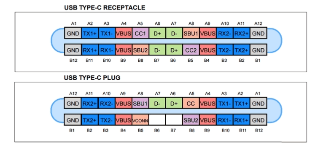
The key difference is that the male plug exposes only one CC channel to the far end. This makes sense: think of a USB-C cable, which is where you normally find male connectors. If the cable internally wired both CC channels straight through, regardless of orientation you would always connect CC1 and CC2 at the same time, making orientation detection impossible. This is not solved at the cable level; it’s solved at the connector level.
Therefore, even if your datasheet shows two CC pins on the plug symbol, make sure that only one is actually tied to your pull-up or pull-down resistor, while B5 remains open. Otherwise, the other end of the USB-C link will never enable VBUS, because the voltages seen on the CC lines will be invalid.
Conclusion
In conclusion, USB-C is a connector that not only makes plugging in easier thanks to its reversibility, but it also introduces a new kind of communication over the CC lines. It’s essential to be clear about what you want from your product so you can predict what will happen when it connects to another device.
Also, remember that USB-PD is a separate communication protocol, also carried on CC, and completely independent of whatever happens with the configuration resistors. Don’t be surprised if, when you’re choosing a USB-C/PD IC, you find parts with MCUs inside as these devices have to run complex state machines, handle the PD protocol, and manage power switches. They’re meant to offload all the PD handling from your main processor, so it’s normal to encounter chips with quite a bit of complexity.
Hope this gave you a clear picture of what USB-C and USB-PD can do. If anything’s still fuzzy, reach out, I’ll be happy to help you dodge a few scorch marks. I hope you have a happy and safe PCB-burning
Stay focused on what’s next
Stories, ideas, and insights from the world of technology, product development, and innovation.




© Copyright 2026 Focus. All Rights Reserved.